Announcement

Collapse
No announcement yet.

Spar-Fusalage Attach Drawings

Collapse
X
 
  • Filter
  • Time
  • Show
Clear All
new posts

  • Spar-Fusalage Attach Drawings

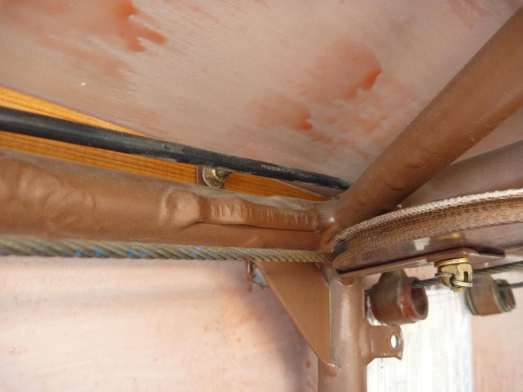
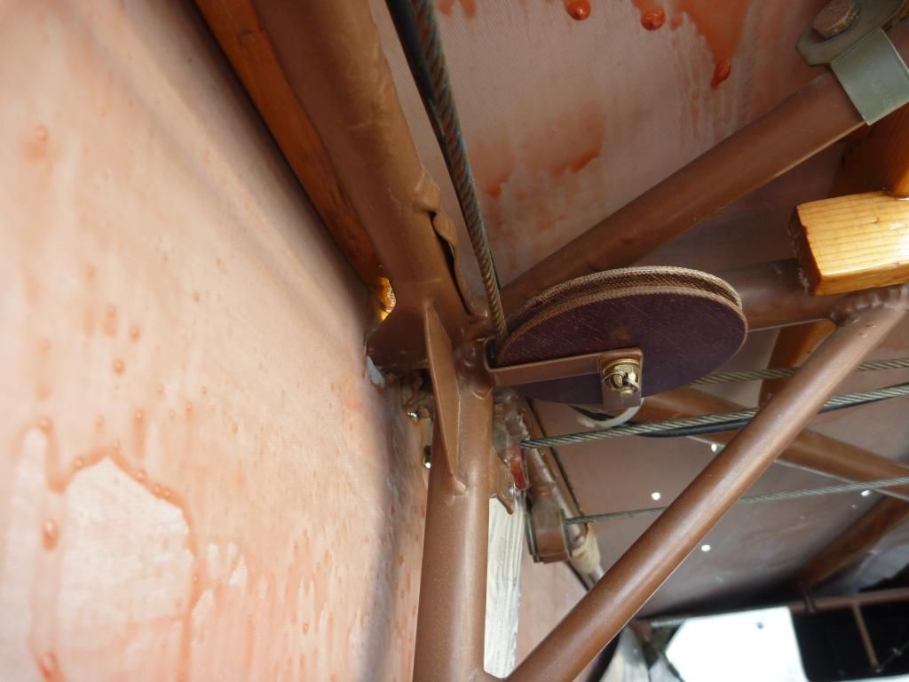
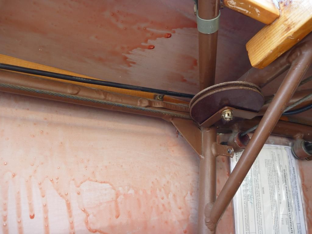
    Long story short I am looking for some engineering drawings that detail the right rear spar to fuselage attach fitting. This summer I did some looking into why my plane is well on the slow side. It seems the most likely cause is a misalignment of the right rear spar to fuselage attach fitting. While looking at the structure I found a tag welded on to the fuselage tubing inside the cockpit, near the attach point. The tag is upside down but reads "T.A.C. M.F.G. Repair". I've attached some pics below. I haven't come across an explanation of this in the log books and I wonder if the frame was damaged on the assembly line and rather than make a note in a new log book the repair was noted with the metal tag. I think the fitting is off by a significant distance causing both wings to be washed fully in opposite directions and the plane to cruise far slower than it should. I have spoken to my mechanic about rewelding the fitting and he would like to see some engineering drawings to get confirmation of the problem.

    Thanks,
    Shaun


  • #2
    Re: Spar-Fusalage Attach Drawings

    Looks like an upper longeron repair. Repairing the upper longeron would NOT change the incidence of the wing and if it was off you would change the distance between the front and rear spar attachments, which would prevent you from even putting the wing on.
    Before cutting and welding anything you first need to fully trammel the plane to look for any other misalignments. If you set your plane up with the top of the stab LEVEL and a string drawn from tip to tip on the wings level you can start measuring the angles of the rest of the plane with an inexpensive Harbor Freight magnetic protractor (REALLY handy device, even when you aren't using it with the magnetic base).
    You need to measure the up or down thrust of the engine, if the cross bar behind the seats is level with the wings, the incidence angle of each wing at several stations along the span (root, strut attach, inboard end of the ailerons and outboard end of the ailerons to start), and how far out of square the tail surfaces are.
    You also need to measure from the rudder hinge to each wing tip (same spot on both sides) to see if your wings have the same sweep (shouldn't be ANY, but many planes are NOT straight!).
    Next I would look carefully at the engine. If there is another plane with the same type engine does your plane run up to the same RPM ON THE SAME PROP? You could have a re-pitched prop and not know it. It would make a BIG difference! It could also be that the other guys engine spins BOTH props to a higher RPM, in which case your engine isn't putting out full HP.

    LOTS of little things to check. When I first got my plane I LOVED the light controls and good cruise and climb she had. Kind of scary when I found out the W&B was WAY OFF and she was actually well aft of the rear CG limit with two people! Sure glad we didn't do any spins in her! DO NOT TRUST someone else s W&B. Do your own and be sure of where the CG is. You could have a well forward CG and that would hurt performance and make the controls heavier than needed too.

    Get some numbers and photos of what you are measuring and we can compare numbers with other planes in the tribe. I have a feeling something else is the problem besides the longeron repair.

    Hank

    Comment


    • #3
      Re: Spar-Fusalage Attach Drawings

      There is a thread from earlier this year in which I detail doing a lot of those things, trading props with another tcraft, weight and balance, measuring incidence of every rib, measuring incidence of spar attach points, etc. http://vb.taylorcraft.org/showthread...hlight=smmilke
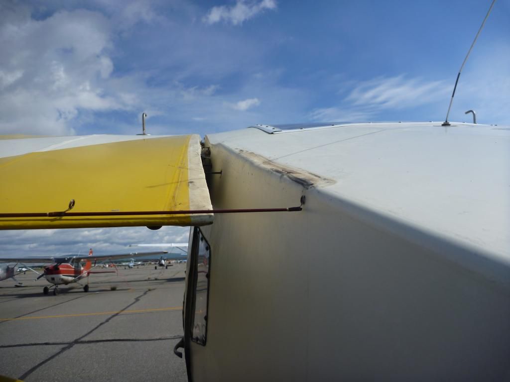
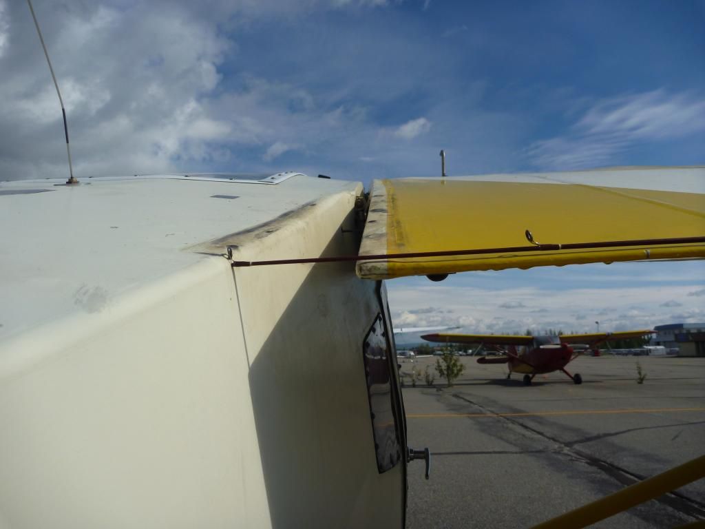
      It really does seem that the right rear attach is misplaced. The most convincing photographic evidence I have, also in the link, is shown below. I am hoping some drawings and measurements with the root fairings off could provide a quick final confirmation.

      Shaun


      Comment


      • #4
        Re: Spar-Fusalage Attach Drawings

        I would measure the distance from the top of the rear spar on both wings to the top of the root rib. Maybe someone built the left wing with the ribs all the way up, relative to the rear spar. And then built the right wing with the ribs all the way down on the spar.
        Richard Pearson
        N43381
        Fort Worth, Texas

        Comment


        • #5
          Re: Spar-Fusalage Attach Drawings

          I've measured as many spots as I can access, on all four spars, to be sure the ribs aren't up on one side and down on another. Making the measurements was tough because of the tight spaces but if I recall correctly all my measurements were fairly precise and all the rib-spar gaps were consistent between spars.

          Comment


          • #6
            Re: Spar-Fusalage Attach Drawings

            Check the incidence angle at the fittings on the fuselage, if the're close, it's in the wings. If the plane has been on it's back, the rear fittings are bent. These little fittings are "tobacco can" thin. The last prewar wings I built I had to make them. The 5 wings I took apart all had bad fittings,but, I didn't know the history of the wings but they show the signs of being flipped.
            EO

            Comment


            • #7
              Re: Spar-Fusalage Attach Drawings

              Hi Shaun,

              A few thoughts;

              1) are your trailing edges straight?

              2) has the plane been rigged according to the service manual instruction?

              3) have the lift struts been damaged?

              4) I see a dent above the left rear spar attach, why isn't that attach point suspect and may be low?

              Dave
              Last edited by Guest; 12-10-2014, 16:00.

              Comment


              • #8
                Re: Spar-Fusalage Attach Drawings

                The incidence at the attach point is not the same for the two wings. The right wing measured 15.5 degrees and the left wing was 16.5 degrees. I set the level on the tops of the two flanges that rest against opposite sides of the spars and tried to get the level closer to the fuselage side of these fittings as that is where they appear to be the most uniform. Despite the precision of these measurements being to .5 degrees, I am not sure the accuracy is really as great as +-.5, due to the difficulty of getting the spacers to sit properly on the uneven tops of the spar attach fittings.

                Dave, to answer you questions:
                1: My trailing edges are quite straight.
                2: The plane was rigged for level flight when new struts were installed. This was before I bought it; it flies well hands off but the wings are washed completely out in opposite directions.
                3: The lift struts have not been damaged.
                4: I believe the "dent" you are seeing is just the transition from wooden former to fuselage tube under the fabric. If you look closely you can see the same thing on the other side. I'm sure this is not an actual dent in the tubing.

                Again, if anyone can point me in the right directions for some drawings it would be fantastic.
                Shaun

                Comment


                • #9
                  Re: Spar-Fusalage Attach Drawings

                  measure from the seat back cross tube up to the attach fitting on both sides. That tube is the leveling point for the airplane.

                  Comment


                  • #10
                    Re: Spar-Fusalage Attach Drawings

                    OK, first of all the positions of the structural hard points make NO DIFFERENCE to the aerodynamics, they are important to the LOADS in the airframe, not the aerodynamics....The structure isn't your problem....yet, and messing with the structure before you know the real problem will make a real mess to fix. All that really makes a difference aerodynamically is the relationship of the CG, thrust line, the mold line of the wing (across the span) and the relationship of those to the mold lines of the tail surfaces.

                    First you need to know the angle of the wing airfoil to the top of the tail plane. NOT the locations of the attach fittings, the MOLD LINE. To do that you need to make a tool that has a notch at the back for the trailing edge and a block to locate the center of the leading edge radius. You want a flat spot for the protractor that is parallel to that line from the center of the radius to the center of the airfoil trailing edge. You level the stab (making sure BOTH SIDES are the same and the fin is perpendicular to it. Until you know that you are wasting your time looking for problems you can't know are the REAL problem. I made mine from a 1x3 piece of poplar with a notched block offset for the TE height and a shaped piece of ply at the front to go around the LE. The rear block slides on to trap the wing for measurement. I used it to find the incidence angle at each rib, but that is a LOT more than was needed. After I was done I realized all I really needed was a small block close to the front spar to hold the stick parallel to the chord line, but you are measuring the AIRFOIL not the spar angle!

                    Once you know the angle between the stab and airfoil at the root the next step is to make sure the wing isn't twisted wrong, but you are wasting your time by skipping steps. Get the angle between the root chord line of the wing to the stab FIRST.

                    Wish Virginia wasn't so far from Alaska. I have the tools from when I did mine and it REALLY isn't that hard.

                    Hank

                    Comment


                    • #11
                      Re: Spar-Fusalage Attach Drawings

                      Originally posted by smmilke View Post
                      The incidence at the attach point is not the same for the two wings. The right wing measured 15.5 degrees and the left wing was 16.5 degrees. I set the level on the tops of the two flanges that rest against opposite sides of the spars and tried to get the level closer to the fuselage side of these fittings as that is where they appear to be the most uniform. Despite the precision of these measurements being to .5 degrees, I am not sure the accuracy is really as great as +-.5, due to the difficulty of getting the spacers to sit properly on the uneven tops of the spar attach fittings.

                      Dave, to answer you questions:
                      1: My trailing edges are quite straight.
                      2: The plane was rigged for level flight when new struts were installed. This was before I bought it; it flies well hands off but the wings are washed completely out in opposite directions.
                      3: The lift struts have not been damaged.
                      4: I believe the "dent" you are seeing is just the transition from wooden former to fuselage tube under the fabric. If you look closely you can see the same thing on the other side. I'm sure this is not an actual dent in the tubing.

                      Again, if anyone can point me in the right directions for some drawings it would be fantastic.
                      Shaun
                      Hi Shaun,

                      Thanks, I get your point about the dent.

                      You can forget about getting the drawings you will never get them. Drawings have been an annoying issue for years. There will lots of talk but never a drawing.

                      If it were mine I would do this next;

                      1) Get the service manual and check wing rigging in accordance with the manual instructions. That particular page is in a .pdf file somewhere on this forum. If I find it I will post it. Here is the link, see page 9 => http://www.taylorcraft.org/docs/tayl...ual%20BB12.pdf

                      2) Use the method prescribed by the manual for setting angle of incidence to measure and compare the root ribs angle of incidence on the LH and RH wing.

                      3) Carefully measure the center to center distance between the bolts on the front lift struts and compare them. I had a similar problem once and the difference was 1/4"

                      4) Stand in front of the plane and observe the horizontal stabilizers. do they (the two of them) form a straight line or are the askew? Also if they make a straight line is that line parallel to the lateral axis of the plane (that seat back cross tube that Mike mentioned). I think that Hank is also describing this check.

                      5) Lastly I am confused. If the plane flies level hands off what problem is that you are trying to resolve? Speed? What do you cruise at?
                      I see from your initial post it is speed, my oversight. What to you cruise at? How are your ailerons rigged? Drooping? Level?

                      Dave
                      Last edited by Guest; 12-11-2014, 03:23.

                      Comment


                      • #12
                        Re: Spar-Fusalage Attach Drawings

                        Hank, as a new Tcraft owner I love learning from your knowledge. Probably a dumb question, but to at least get an idea if my W & B paperwork is close to accurate can I use just regular scales that people use? I know it would not be official, but maybe give an indication. My 1946 seems to fly pretty close to book numbers, granted it's a C85 and I wouldn't call the pitch force light or heavy, but I don't have any other Tcraft to compare to.

                        Thanks

                        Comment


                        • #13
                          Re: Spar-Fusalage Attach Drawings

                          You can use bathroom scales to check it with but it will not be legal. Keep in mind you will need 3 very closely calibrated scales to be anywhere near close and you have to weigh all 3 wheels of the airplane at the same time in level attitude.
                          Kevin Mays
                          West Liberty,Ky

                          Comment


                          • #14
                            Re: Spar-Fusalage Attach Drawings

                            You need scales that are accurate at close to the weight you are going to measure (real word SAFE way to do it). Lots of really inexpensive electronic scales out there now and the ones I have checked were more accurate than the "certified" scales (I check my scales with a known weight). Does someone know of a restriction on using commercial scales? I must have missed that one. I thought as long as they are verified they should be OK. I sure trust the three electronic scales I have more than the ones our EAA chapter has that are "official". Those are old beam scales and I don't know who has checked them or when.

                            Hank

                            If someone knows of a reg requiring "official" scales I would appreciate the education.

                            Comment


                            • #15
                              Re: Spar-Fusalage Attach Drawings

                              I'm with you Hank...I think (dusting off the cobwebs here) that the parameter was "calibrated" scale. I always used a friend's electronic scales that he has for his race car...he sends them in twice a year for calibration...they're a WHOLE lot more accurate than the old beam scales.
                              John
                              I'm so far behind, I think I'm ahead

                              Comment

                              Working...
                              X