
Re: Harer STC Questions
REAL HAPPY with the info from you guys!
I've worked on aircraft since the Nina & Pinta projects were completed but
DO NOT consider myself an EXPERT on every particular type.
My opinion is EVERY aircraft owner should join the appropriate Type Club.
It appears that the Wing Attach Fittings on the fuselage do NOT require
any reinforcement per the STC.
Victor Bravo is absolutely right in recommending Teflon hose. (Type D)
Most mfg. state a replacement time of 5 to 10 years otherwise.
For very few $$ more the Temp Rating goes from 250 degrees to 450 degrees.
This is really significant on aircaft where a oil hose is near the exhaust (PA28-140).
We had 2 incidents is this area alone where the hose ruptured.
Engine became a PAPERWEIGHT very quickly!
-
Re: Harer STC Questions
We may have to cut some fabric to remove the bundled up vent system from
the wings.
After connecting per STC the plan is to add a "Tee".
AFTER the aircraft is back in service if there is a feed problem it would enable
a "vent test" in a more logical location.
The first 172's used a Top Vent System.
Cessna gave up on that real quick & for over 50 years it's UNDER the wing.
This is in the HIGH Pressure area & behind the strut to shield from ice & bugs.
Leaky cap gaskets cause fuel stains behind the filler.
Seems to me that regardless of tube size the Cap Vent system would always be less effective.Leave a comment:
-
Re: Harer STC Questions
On 20442, a '39. Left wing tank valve at the root, I hang an old digital watch from the valve handle for timing the fuel in both tanks. It hangs down just far enough below the top of the door frame to remind me or the pax to mind our head.
You guys experiencing flow problems from the wing tanks might want to check the gas cap gaskets. Worn seals can contribute to sluggish flow. Make sure that the correct fuel tank cap is installed, unless you like proving that you can land on that random field in the mountains....... ops:
ops:
Leave a comment:
-
Re: Harer STC Questions
My plane had the wing tank valves located at the wing root. After drawing blood the third time from my balding pate, I decided to move them to under the panel. I took my plane to the IA I bought if from and worked with one of his mechanics to relocate the valves. When the mechanic asked me where I wanted the valves located, I sat in the plane and held the valves under the instrument panel directly between my knees. He fabricated brackets out of sheet aluminum, and held them in place with Adel clamps. We used fuel lube on all the fittings and tightened them SLOWLY. When they wouldn't tighten any more we waited for the heat from the friction to cool down, and then tightened them some more. I have never had a leak or drawn blood on the valves since. I intend to put the valves under the panel on my project plane also. It is the only way to go in my opinion.Leave a comment:
-
Re: Harer STC Questions
On occasion, in any one of my 12D's I have found it necessary to wag the wings or do a couple of up and downs, maybe 2 Gees to get the fuel flowing from the wing tanks.
The one I have now has 2 tanks in the wings and a 3 way valve under the control column. Used to give me some problems occasionally, but has been 100 percent OK for quite some time now. Strangely the valve handle, which is normally straight down, has never been a problem. You would think it would be kneecap city all the time. Should check why it isn't in the way, I guess.
DarrylLeave a comment:
-
Re: Harer STC Questions
All good points Bill I can see problems with both locations. my latest project has had a single shut off mounted above the control column since the 50,s I believe, so I am thinking of leaving it there. carltonLeave a comment:
-
Re: Harer STC Questions
Looks like the fuel valves got switched a lot too. My 45 has the valves in the wings (early 45 serial number) and the 41 has it under the panel. Might as well put it back in the wing root while I am working on the plane. I can learn to remember to shut it off before getting out of the plane. I ALWAYS bash my knee on it in the 41, only once hit my head (but it was a GOOD one, staggered around and ended hanging on to a strut for a while).
Hank
[QUOTE=Forrest Barber;48110]A lot of Taylorcrafts were changed around over the years....that vent is completely wrong. One of many requests I have for drawings is that one.
All 41's had the fuel valve at the Wing tank. All BC12D after a certain ser# in 45-46 ahd it under the panel where it belongs. That extra "slug" of fuel in the line will facillate the transfer. ( IMHO!)Leave a comment:
-
Re: Harer STC Questions
Also Spracht Zarathustra ! Finally a mystery solved, thank you sincerely Forrest. We'd really like to know more about some of the "back story" behind some of CG's or Jack Gilberti's decisions. Who knows, I may have to eat some crow on a couple of points.Originally posted by Forrest Barber View Post
For the IA helping Gallager, THANK YOU for helping him put things right and keeping another T-craft out of an accident. On behalf of the entire group I can say we will be as much help as possible on an informational level. The wing tanks should have a pitot style vent in the cap and not inside the wing, that's crazy.
From personal experience, the cap vent is a marginal (but OEM and approved) method. If you want to add more safety to the situation, I recommend extending the pitot vents on the caps forward as far towards the leading edge as possible to get it into a higher ambient pressure area. That will be at your discretion as an IA.Leave a comment:
-
Re: Harer STC Questions
A lot of Taylorcrafts were changed around over the years....that vent is completely wrong. One of many requests I have for drawings is that one.
All 41's had the fuel valve at the Wing tank. All BC12D after a certain ser# in 45-46 ahd it under the panel where it belongs. That extra "slug" of fuel in the line will facillate the transfer. ( IMHO!)
There is the story of C.G. trying to transfer fuel enroute to Florida one time, it would not transfer; he whipped out his ever present pen knife , cut out into the wing root and "bonked" the tank with his fist to start the transfer. A man of Action! :beerchug:
The "shear" plate was a method to facillate production as was the little triangles on the upper wing attach fittings ont he fuselage. They keep things in alingment duirng production and assembly. I now recall taht we do ahve one older engineer still alive within 25 miles. I will be asking him. We have many engineering considerations that need answers , a lot of data is in the back room, so little time. bye off to airport duties & then calls on the new project., Taylorcraft 2000LLC.Leave a comment:
-
Re: Harer STC Questions
I'm the IA working with Gallager. When he says some things were "not quite right" he is being kind. Fuselage tank was vented into the cockpit where
your feet could get wet. Wing tank vent lines are inside the wing.
A ACS experimental gascolator provides (?) fuel to the carburetor in a unusual fashion. That is through a 1/8 NPT outlet normally used for
the primer. See WHY we're concerned?
Ron CiuraLeave a comment:
-
Re: Harer STC Questions
Wow, I must have a bad rep for freaking out on people... sorry to all for that. I'll try to scale back on whatever causes people to think that.Originally posted by t-crafter View Post
It is much much safer in my opinion to have the fuel shutoff valves in the wing root. With them there, you can stop fuel flow to a leak in the alum. fuel line and in the connections to the main tank. With the valves down under the panel, a leak in the aluminum fuel line will still fill the cockpit with 6 gallons of gas. With the valve down under the panel, you have several leak points (fittings, the valve itself, connections, etc) near the ignition switch and near anything resembling wiring or an electrical bus, etc. They are much easier to see and verify the valve position when they are at eye level in plain sight. As Hank points out they are a hazard to smashing into no matter where they are... take your pick of scalp or knees.Leave a comment:
-
Re: Harer STC Questions
This should be an interesting answer from Bill. In MY case, the 41 has the lever under the panel where it rips your knee open whenever you are transferring fuel. You WILL NOT forget to shut it off as soon as you can. On the 45 they (two tanks) are on the wing root over the door, where it is much easier to forget to shut them off immediately. You will remember when you get ready to leave the cockpit as they rip your scalp off. I hate them in both places and don't use the wing tanks (at least not unless I have to).
HankLeave a comment:
-
Re: Harer STC Questions
Bill, why don't you like moving the fuel shut offs down under the instrument panel ? Having the shut off valve in the wing rout is hard on the head unless you wear a helmet. It is just a question, don't freak out on me now! CarltonLeave a comment:
-
Re: Harer STC Questions
As to the vents (and bigger fuel lines from the wings to the fuselage), they have no engineering value whatsoever. They must have been put in for some reason, certainly not for fuel flow purposes. My fuselage tank fills up just like it did with the old 65. Your legal situation might be different, however.Leave a comment:
-
Re: Harer STC Questions
They make sense to me, although I would struggle to quantify it too much.Originally posted by VictorBravo View Post
Suffice to say that one of the weakness of the "two-piece" approach to this fitting design is that the load caused by the angle between the front & rear struts on those metal pieces tend to make each fitting, which normally comprises two separate pieces, form a parallelogram, rather than remain "square".
This is because the front & rear spars are parallel, and hence these fittings, are parallel. But because the struts are not, the tensile loads of the struts pull the front & rear fittings together.
Imagine lying on your back under a wing, with your feet under the fuselage and your body stretching in a summer pose to avoid sunburn, towards the wingtip. Looking up and arching your neck back slightly to avoid the scratch of the straw on the nape of your neck, you will be looking directly at the widespread attachment of the front & rear struts where they attach to the wings.
You may note that there is a compression strut (under the fabric) on the wing between the front & rear spars between these fittings (I assume to minimise the "parallelogram" effect).
In flight, these angled loads tend to twist the front & rear spar fittings towards each other (and hence the bolts through each spar), inducing compression of the wood fibres, leading to weakness. The welded plate reduces this by ensuring each pair of pieces in each fitting remain parallel.
I'm surprised the design wasn't so from the word go, knowing CG's attention to detail.
For illustration, here is the fitting without the plate (ignore the cylindrical polished spacers...they were there just as spacers for welding purposes) :
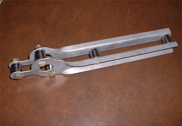
...and here is the fitting with the plates welded on. What you see here is the large flat plate seen under the fitting when it's installed on the wing. Not obvious in this second photo is that there is a smaller plate welded on the opposite side. This stiffens up the whole assembly quite dramatically:

RobLeave a comment:
Leave a comment: